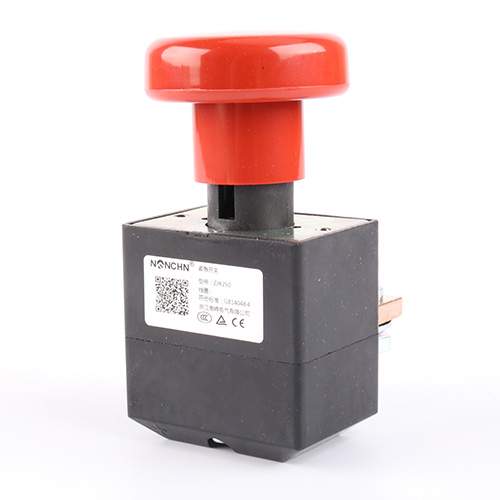

You're standing next to an electric forklift or a battery-powered winch, and the main contactor inside has to connect or disconnect a 500A DC circuit without welding its contacts together or eroding them into scrap. A DC Contactor built for this duty uses a bridge-type contact structure and a dedicated arc chute to control the energy that appears when the circuit opens under load. This article explains how the bridge contacts share the current, what the ceramic arc chute does to extinguish the DC arc, and what to verify when you're selecting a contactor for a battery vehicle or industrial DC system.
How Does the Bridge Contact Structure Share 500 Amps?
Two Contact Points Instead of One
A bridge-type contact uses a moving bar that presses across two fixed contact points. When the coil energizes, the bar closes the circuit at two locations simultaneously. That double contact point splits the current into two parallel paths, reducing the current density at each contact face and lowering the heat generated per point.
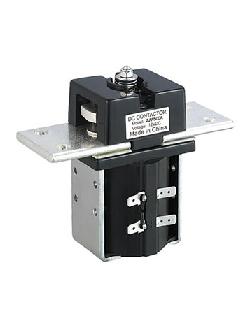
The ZJW500A uses one pair of bridge-type normally open contacts rated at 500A. The voltage drop across the contacts is ≤80mV, which is the electrical signature of a low-resistance interface. At 500A, that 80mV corresponds to about 40W of heat at the contact — manageable for a well-designed contactor, but enough to cause problems if the contact resistance rises.
Why AgCuO(10) Contact Material Resists Erosion
The contact material is AgCuO(10)/Cu. Silver-copper oxide combines silver's high conductivity with copper oxide's resistance to arc erosion and contact welding. At 500A, the contact faces see enough energy during opening to pit and erode a pure silver surface. The AgCuO(10) composite resists that erosion, so the contactor maintains its current-carrying capacity across thousands of operations.
What Does the Ceramic Arc Chute Do to Extinguish the Arc?Labyrinth Geometry Stretches the Arc
DC arcs don't self-extinguish at zero crossings the way AC arcs do. When the contacts open under load, the arc sustains itself until the gap is long enough or the arc is cooled below the ionization threshold. A contactor without effective arc management will erode its contacts rapidly and may fail to interrupt the circuit at all.
The ZJW500A uses a labyrinth-type ceramic arc chamber combined with an arc-resistant plastic cover. The labyrinth geometry stretches the arc along a folded path, increasing its length and cooling it as it travels. The ceramic material withstands the arc's heat without tracking or degrading, and the labyrinth structure keeps the arc from escaping the chamber. For coil voltages above 48V, a magnetic blowout device pushes the arc away from the contact gap and into the chute more quickly, reducing dwell time on the contact faces.
| Parameter | ZJW500A Specification |
|---|---|
| Contact type | One pair of bridge-type NO contacts |
| Rated contact voltage (DC) | ≤80V |
| Rated contact current | 500A |
| Instantaneous max closing current | 7Ie, ≤1s |
| Voltage drop on contacts | ≤80mV |
| Coil voltage options (DC) | 12V, 24V, 48V, 72V, etc. |
| Coil power consumption | ≤16W |
| Pickup voltage | ≤75% Us |
| Release voltage | ≥5% Us; ≤40% Us |
| Pickup time | ≤30ms |
| Release time | ≤50ms |
| Contact material | AgCuO(10)/Cu |
| Mechanical life | ≥30×10⁴ cycles |
| Electrical life | ≥2×10⁴ cycles |
| Protection grade | IP50 |
| Working temperature | -25°C to +55°C |
What Coil Options Control the Switching Action?
Pickup, Release, and Timing
The coil is the control element. When it receives its rated voltage, the electromagnetic force pulls the moving contact bar down and closes the bridge contacts. The pickup voltage is ≤75% of rated, so the contactor pulls in reliably even when battery voltage sags under load. The release voltage sits between 5% and 40% of rated, ensuring a clean drop-out without chattering at intermediate voltages.
The pickup time is ≤30ms and the release time is ≤50ms, fast enough for most battery vehicle and winch control sequences.
Coil Resistance and Power Consumption
The standard coil voltage options are 12V, 24V, 48V, and 72V DC, with other voltages available. Coil resistance varies by voltage: a 12V coil measures around 17.1Ω, a 24V coil around 67.7Ω, and a 48V coil around 210.4Ω at 20°C. Higher coil resistance means lower holding current, which reduces the drain on the battery while the contactor is energized.
The coil power consumption is ≤16W. That figure matters in battery-powered equipment where every watt of continuous draw reduces runtime.
Where Does This Contactor Get Used in Battery-Powered Equipment?
The ZJW500A is designed to control the switching on and off of power supply in storage battery cars, electric forklifts, electric winches, electric cars, excavators, and vehicle air conditioners. The common thread is a DC system that runs at up to 80V and carries high current — 500A continuous, with a 7× rated current instantaneous closing capacity for inrush events.
In an electric forklift, the contactor sits between the battery pack and the traction controller. In a winch, it switches the motor power. In an excavator, it isolates the battery from the DC auxiliary systems. The contactor's job is always the same: connect and disconnect the battery safely, without welding or excessive erosion.
The contacts can also be used for AC loads of 380V, 220V, and 110V, as noted in the product documentation. That dual AC/DC capability makes the contactor usable in mixed panels where a DC battery system and AC auxiliary circuits coexist. The arc chute is designed primarily for DC interruption, but the AC ratings cover lower-energy AC switching where the zero crossing helps extinguish the arc.
A DC Contactor like the ZJW500A is built for these high-current battery and industrial applications. The bridge contact structure, AgCuO(10) contact material, and labyrinth ceramic arc chute work together to handle 500A switching without the contact erosion that shortens service life.
What Should You Check Before Installing a 500A Contactor?
Coil Voltage Matching
Match the coil voltage to the control circuit, not the main power circuit. If the battery pack is 48V and the control circuit runs directly from the battery, use a 48V coil. If the control circuit runs through a DC-DC converter at 24V, use a 24V coil and switch the higher-voltage main circuit through the contacts. Connecting a 24V coil to a 48V supply will overheat and damage the coil.
Continuous Duty Rating
The ZJW500A is rated for continuous operating duty. That means the coil can stay energized indefinitely without overheating, as long as the ambient temperature stays within the -25°C to +55°C range. Using an intermittent-duty contactor in a continuous application will burn out the coil.
Maintenance and Inspection
Inspect the contact faces for pitting and erosion during periodic maintenance. A contact face that has eroded significantly will have a higher voltage drop and will generate more heat. Check the arc chute for cracks or buildup of arc debris — a damaged chute loses its arc-stretching effectiveness. Verify the coil terminals for tightness and check the moving mechanism for smooth operation without binding.
Straight Answers on High-Current DC Contactors
What causes a DC contactor to weld shut?
Welding happens when the contacts close on a high inrush current and the contact faces fuse together before they can separate. The AgCuO(10) material resists welding, and the bridge structure distributes the closing force across two points. But welding can still occur if the contactor is undersized for the inrush current or if the contacts are badly eroded. Match the instantaneous closing rating to the load's inrush characteristic.
Why does voltage drop matter at 500A?
At 500A, even a small resistance produces significant heat. A voltage drop of 80mV at 500A corresponds to 40W of heat at the contact interface. That heat raises the contact temperature, which accelerates erosion and reduces service life. A contactor with a higher voltage drop runs hotter and fails sooner.
Can the contactor switch the load in both directions?
The ZJW500A has normally open contacts, so it makes the circuit when the coil is energized and breaks it when the coil is de-energized. It doesn't reverse the current direction. For applications that need forward and reverse, two contactors are used in a reversing configuration, with interlocking to prevent both from closing at the same time.
What's the purpose of the magnetic blowout on higher-voltage coils?
The magnetic blowout uses a magnetic field to push the arc away from the contact gap and into the arc chute. At higher coil voltages, the available energy for arc interruption is greater, and the arc can linger on the contact faces if it isn't moved quickly. The blowout accelerates the arc transfer, reducing contact erosion and improving interruption reliability.
Let's Specify a DC Contactor for Your Battery System
Share Your Voltage, Current, and Duty Cycle
A DC Contactor should match your system voltage, continuous current, inrush profile, and duty cycle — not the other way around. The ZJW500A from Nanfeng Electric handles 500A at up to 80V DC, with bridge-type NO contacts, AgCuO(10) contact material, a labyrinth ceramic arc chute, and coil options from 12V to 72V DC. The contactor is rated for continuous duty, with ≤80mV voltage drop and a 7× rated current instantaneous closing capacity for inrush events. If you're specifying a main contactor for a battery vehicle, forklift, winch, or excavator, send us your system voltage and current requirements — we'll help you confirm the right configuration before you order.