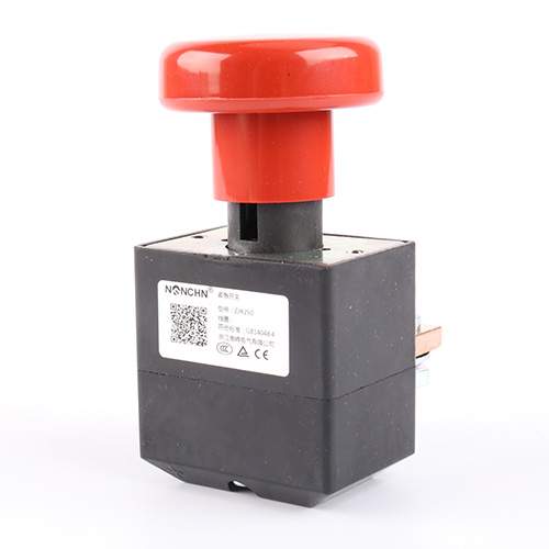

You’re looking at the main power switch inside an electric bus or a DC fast charger, and the contactor has to break a 750V DC circuit while carrying 200A. Unlike AC, DC has no zero-crossing to help extinguish the arc—the arc sustains itself until the gap is wide enough or the plasma cools below the ionization threshold. A DC Contactor in the fully sealed configuration solves that by enclosing the contacts in a hermetically sealed chamber filled with inert gas, so the arc is cooled and suppressed in a controlled atmosphere. The TG200H from Nanfeng runs this architecture at 750V/200A with IP67 protection and an operating range of -40°C to +85°C. This article explains how the sealed chamber quenches the arc, what the bridge contact geometry contributes, and what to verify when you're specifying a contactor for an EV or charging application.
Why Does DC Arcing Need a Sealed Chamber?
No Zero-Crossing, No Natural Extinction
In an AC circuit, the current passes through zero twice per cycle. At each zero-crossing, the arc momentarily extinguishes, and if the dielectric strength recovers faster than the voltage rises, the arc stays out. DC has no such crossing. Once the arc strikes, it continues until the gap length or the cooling effect brings the plasma below the ionization threshold. That’s why DC contactors need a dedicated arc-management strategy rather than relying on the natural behavior of the current waveform.
Inert Gas and the Arc-Cooling Effect
The TG200H seals the contact chamber and fills it with inert gas. The gas displaces oxygen, which prevents contact oxidation and keeps the contact resistance stable over time. More importantly, the gas provides a cooling medium for the arc. As the arc travels through the gas, heat is conducted away from the plasma column, and the arc’s temperature drops faster than it would in air. That accelerated cooling shortens the arc duration and reduces the energy that reaches the contact faces.
The sealed chamber also prevents the ionized gas and metal vapor from escaping into the surrounding environment. In an EV or charging cabinet, that containment matters for safety and for maintaining the dielectric integrity of the surrounding components.
What Does the Bridge Contact Geometry Contribute?
Two Gaps in Series
The TG200H uses one pair of bridge-type normally open contacts. A bridge contact has a moving bar that bridges across two fixed contact points. When the bar lifts, two gaps open in series instead of one. The total arc voltage is split across both gaps, which reduces the voltage stress on each gap and helps the arc extinguish faster.
The bridge geometry also distributes the current across two contact points during normal conduction. That distribution lowers the current density at each contact face and reduces the heat generated per point. The contact voltage drop is held to ≤100mV at 100A, which is the electrical signature of a well-designed contact interface.
AgCuO(10) Contact Material
The contact faces are made from AgCuO(10) —silver-copper oxide. Silver provides the high conductivity needed for low contact resistance. The copper oxide phase adds resistance to arc erosion and contact welding. In a high-voltage DC circuit, the contact faces see enough energy during opening to pit and erode a pure silver surface. The AgCuO(10) composite resists that erosion, so the contactor maintains its current-carrying capacity across the rated electrical life.
| Parameter | TG200H Specification |
|---|---|
| Contact form | 1 bridge-type NO (1H) |
| Rated contact load (DC) | 750V, 200A |
| Contact voltage drop | ≤100mV (at 100A) |
| Instantaneous max current | 800A, ≤1s |
| Max breaking current | 2000A (at 320VDC), 1 operation |
| Electrical life (750V, 200A) | ≥1,000 operations |
| Electrical life (450V, 200A) | ≥5,000 operations |
| Pickup time | ≤30ms |
| Release time | ≤20ms |
| Coil voltage options (DC) | 12V, 24V, etc. |
| Coil holding power | ≤4.0W |
| Mechanical life | ≥300,000 operations |
| Dielectric withstand (contact-to-coil) | 2200VAC, 1min |
| Protection degree | IP67 |
| Operating temperature | -40°C to +85°C |
| Mounting | Any orientation |
How Does the Coil Control the Switching Action?
Pickup, Release, and Holding Power
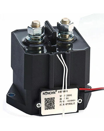
The coil is the control element. When it receives its rated voltage, the electromagnetic force pulls the bridge bar down and closes the contacts. The pickup voltage is ≤75% of rated, which means the contactor pulls in reliably even when the battery voltage sags under load. The release voltage is ≥7.0V, ensuring a clean drop-out without chatter at intermediate voltages.
The coil holding power is ≤4.0W. That figure matters in battery-powered equipment where every watt of continuous draw reduces runtime. A contactor that holds at 4W is easier on the auxiliary battery than one that draws significantly more. The operating frequency is ≤1Hz, reflecting the contactor’s role as a main power switch rather than a high-frequency cycling device.
Long-Term Coil Duty
The coil is rated for long-term operation. It can stay energized indefinitely without overheating, as long as the ambient temperature stays within the -40°C to +85°C range. That continuous-duty rating is what allows the contactor to serve as the main power connection in an EV, where the coil may remain energized for the entire duration of a drive cycle.
Where Does a Sealed Contactor Fit in EV and Charging Systems?
Electric Buses, Passenger EVs, and Charging Piles
The TG200H is designed for electric buses, charging piles, electric vehicles, automotive air conditioning, and telecom power systems. In an electric bus, the contactor sits between the battery pack and the traction inverter, switching the main DC power path. In a DC fast charger, it isolates the charging connector from the internal DC bus when the session ends. In automotive air conditioning, it switches the high-voltage compressor circuit.
The IP67 rating and the sealed chamber make the contactor suitable for installations where moisture, dust, and vibration are present. The any-orientation mounting allows it to fit into the confined spaces inside a vehicle chassis or a charging cabinet.
750V and 1000V System Compatibility
The TG200H is rated for 750V DC at 200A continuous. The electrical life data shows ≥1,000 operations at 750V/200A and ≥5,000 operations at 450V/200A. For higher-voltage systems, the sealed architecture and inert-gas filling support operation at 1000V DC with a derated continuous current. The instantaneous maximum current is 800A for up to 1 second, which provides headroom for the inrush that occurs when a capacitive load is connected.
A DC Contactor like the TG200H from Nanfeng combines the sealed chamber, bridge contact geometry, and AgCuO(10) contact material in a package rated for IP67 and -40°C to +85°C. The 2000A breaking current at 320VDC covers the fault-clearing requirement in a low-voltage DC system, and the ≤30ms pickup time supports the fast sequencing that EV power-up and charging handshakes require.
What Should You Check Before Selecting a Sealed Contactor?
How do I match the contact rating to my system voltage?
The TG200H is rated at 750V/200A for continuous duty. If your system operates at a higher voltage, confirm the derated current and the breaking capacity at that voltage. The electrical life table shows that the operation count drops as the voltage rises—5,000 operations at 450V/200A versus 1,000 operations at 750V/200A——so the voltage margin directly affects the service life.
What coil voltage do I need?
The standard coil options are 12V DC and 24V DC. Match the coil to the control circuit, not the main power circuit. If the vehicle has a 12V auxiliary system, use the 12V coil. If the control system runs at 24V, use the 24V coil. Connecting a 12V coil to a 24V supply will overheat and damage the winding.
What environmental limits apply?
The operating temperature is -40°C to +85°C, and the contactor withstands 2.5g sine vibration from 5 to 50Hz and 50g shock for 11ms. The IP67 rating protects against dust and water ingress. Check that the installation location stays within those limits; if the contactor sits near a heat source or in a washdown area, confirm the ambient conditions before finalizing the specification.
What maintenance does a sealed contactor need?
The sealed chamber has no user-serviceable internal parts. Inspect the terminals for tightness and the housing for mechanical damage during periodic maintenance. The M8 terminal torque should not exceed 9.0 N·m——over-tightening can crack the housing or deform the terminal. Verify the coil terminals and the control wiring for secure connections.
Straight Answers on Fully Sealed Contactors
What's the difference between a sealed and a vented contactor?
A vented contactor allows the arc products to escape into the surrounding air. A sealed contactor contains the arc and the ionized gas inside the chamber, using the inert gas filling to cool the arc and prevent contact oxidation. The sealed design is required for high-voltage DC and for environments where the arc products cannot be released safely.
Why is the contact chamber filled with inert gas?
The inert gas displaces oxygen, which prevents the contact surfaces from oxidizing between operations. It also provides a cooling medium for the arc. When the contacts open, the arc heats the gas, and the gas conducts heat away from the plasma column, shortening the arc duration and reducing erosion on the contact faces.
Can the TG200H be used in both directions?
The main contact circuit is non-polarized——the contactor can be connected in either polarity without affecting the switching performance. That flexibility simplifies the wiring in a battery system, where the positive and negative conductors may be routed differently depending on the vehicle layout.
What causes a sealed contactor to fail?
The most common failure modes are contact erosion after the rated electrical life is consumed, coil burnout from an overvoltage condition, and mechanical wear of the bridge bar after the rated mechanical life. The ≥300,000 mechanical operations and ≥1,000 electrical operations at 750V/200A define the service window. Operating beyond those limits, or exceeding the rated voltage or current, accelerates the wear.
Let's Match a Sealed Contactor to Your DC System
Share Your Voltage, Current, and Environmental Requirements
A DC Contactor in the fully sealed configuration should match your system voltage, continuous current, and environmental exposure—not the other way around. The TG200H from Nanfeng handles 750V/200A continuous with 800A instantaneous maximum, uses a bridge-type normally open contact in a hermetically sealed inert-gas chamber, and carries IP67 protection across a -40°C to +85°C operating range. The AgCuO(10) contact material and ≤4.0W coil holding power suit electric buses, passenger EVs, charging piles, and telecom power systems. If you're specifying a main contactor for a high-voltage DC application, send us your voltage, current, and environmental requirements — we'll help you confirm the right configuration before you order.