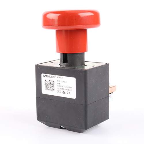

An Emergency Switch has one job: when a person pushes it, the power goes off. The ZJK125 does that with a red mushroom head acting on a mechanical limit design, so the force the operator applies is transmitted directly to the contact mechanism. You'll see why that direct path matters, what the 125A DC ratings cover, and where the response times and forces sit.
What Questions Come Up Before Specifying a DC Emergency Stop?
Why not use a relay or contactor for emergency disconnection?
A relay or contactor opens when its coil is de-energized, which means the disconnection depends on control power being present and on the control circuit functioning. In a fault that takes out the control supply, that dependency is exactly what you can't rely on. The page lists the Emergency Switch as using a red mushroom head handle to control on and off, with a mechanical limit design. The push travels through the mechanism to the contacts—no coil, no logic, no control power in the path.
What does “mechanical limit design” change about the switching?
The page lists mechanical limit design as the operating principle. The limit fixes how far the contact mechanism travels when the button is pressed, so the opening distance doesn't depend on how hard the operator pushes. That repeatability is what makes the disconnect predictable: every press opens the contacts to the same point, and the switch behaves the same way on the first operation and the thousandth.
The Mechanical Path and the Response Time
The push force is listed as 20.0–30.0N, and the closed pull force is also 20.0–30.0N. Those two figures define the feel of the switch: the operator applies a force within that window, and the mechanism responds. The normal disconnection time is ≤50ms, and the normal closing time is ≤100ms.
The disconnection time is the figure that matters for an Emergency Switch. In 50ms, the contacts have separated and the arc has been interrupted. For a DC circuit at ≤80V and up to 125A, that arc interruption is the moment the current path is broken—and the direct mechanical action is what makes it happen without a delay for coil de-energization or control logic processing.
| Parameter | ZJK125 (from the product page) |
|---|---|
| Contact type | One pair of bridge type |
| Rated contact voltage (DC) | ≤80V |
| Rated contact current | 125A |
| Instantaneous max closing current | 600A, ≤1s |
| Voltage drop on contacts | ≤80mV (at 100A) |
| Insulation resistance | ≥100MΩ (DC500V) |
| Dielectric withstand | 1500V, 1 min, no breakdown |
| Normal closing time | ≤100ms |
| Normal disconnection time | ≤50ms |
| Disconnect thrust / closed pull force | 20.0–30.0N each |
| Mechanical cycles | ≥2×10⁴ |
| Electric cycles | ≥1×10⁴ |
| Protection grade | IP50 |
| Contact material | AgCuO(10)/Cu |
| Working temperature | -25℃ to +55℃ |
Why the 50ms disconnection time depends on the contact gap
A mechanical switch opens at a speed set by the mechanism's spring and the contact gap. The page lists a bridge-type contact pair. The ≤50ms figure is the time from the push to the contacts separating and the arc extinguishing—and that time is a function of how fast the mechanism moves the bridge away from the fixed contact. The 20–30N operating force is the input that drives that motion, and the mechanical limit is what stops it at the designed gap.
The DC Envelope: ≤80V at 125A
The ZJK125 is rated for DC contact voltage of ≤80V and a rated contact current of 125A. The page also lists an instantaneous maximum closing current of 600A for ≤1 second. That's a specific DC envelope: the switch is built for battery vehicle, forklift, electric vehicle, and excavator DC systems, not for AC distribution.
The 600A closing window matters on the make side. When the switch is reset or when the circuit is made under load, the contact faces can see a brief surge well above the 125A continuous rating. The 600A / 1s margin is what the contact assembly is designed to absorb without welding or pitting.
-
Rated current: 125A continuous
-
Rated voltage: DC ≤80V
-
Closing surge: 600A for ≤1s
-
Contact material: AgCuO(10)/Cu, silver-copper oxide on copper
-
Contact form: one pair of bridge type
Why silver-copper oxide suits a DC breaking contact
AgCuO(10)/Cu pairs a silver-copper oxide face with a copper backing. The silver oxide face resists welding and arc erosion under repeated DC making and breaking, where a DC arc doesn't have the natural zero crossing that helps an AC contact extinguish. The copper backing carries the current and gives the contact its mechanical support.
Sealing, Temperature, and the Installation Envelope
The protection grade is IP50, and the working temperature range is -25℃ to +55℃. The page lists a vibration rating of 2.5g across 5–50Hz and an impact rating of 50g for 11ms half-sine. Those aren't lab formalities—they describe a switch mounted on a forklift chassis or an excavator frame, where road shock and engine vibration reach the contact mechanism directly.
-
Protection grade: IP50, dust-protected but not water-jet rated
-
Temperature: -25℃ to +55℃, covering vehicle and outdoor cabinet conditions
-
Vibration: 2.5g, 5–50Hz sine
-
Impact: 50g, 11ms half-sine
-
Mounting: freely mounted, no single prescribed orientation
-
Terminal torque: M10 outgoing terminal, not more than 4.5 N·m
Why free mounting matters on a retrofit
A switch that doesn't require a fixed orientation is easier to fit into an existing battery box or control cabinet. The installer can route the cables and position the mushroom head where the operator can reach it, rather than rebuilding the mounting plate to suit the switch. For aftermarket and retrofit work, that flexibility often decides whether a job takes an hour or a day.
Where the ZJK125 Fits the DC Circuit
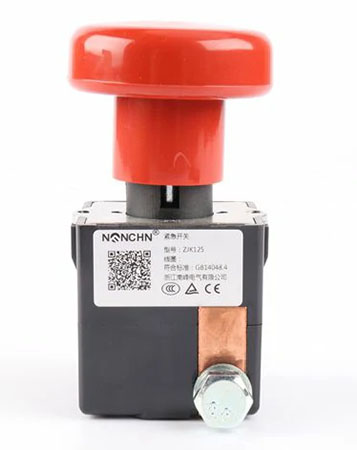
The Emergency Switch ZJK125 from dc-contactor.com is built around the direct mechanical action the page describes: a red mushroom head driving a mechanical limit mechanism to open a 125A / DC≤80V circuit in ≤50ms, with a 600A closing surge margin and AgCuO(10)/Cu contacts. The IP50 enclosure, -25℃ to +55℃ range, and 2.5g vibration rating place it in vehicle and mobile equipment applications. For a battery vehicle, forklift, electric vehicle, or excavator builder, the value sits in the direct path—the operator's push is the only thing between the fault and the open circuit, with no coil, no control power, and no logic to fail.
What to confirm before matching a switch to a DC system
Confirm the continuous current against the 125A rating, the system voltage against the DC≤80V limit, and the closing surge against the 600A / 1s window. Check the mounting location against the IP50 rating and the temperature range, and the operating force against the access the operator has to the mushroom head. The page's ratings give the starting point; the actual circuit and the installation determine whether the standard configuration fits.
Let's Match an Emergency Switch to Your DC Circuit
Send over your system voltage, continuous current, closing surge, and mounting location—we'll help you check them against the 125A / DC80V rating, the 600A closing window, and the IP50 enclosure. Talk to dc-contactor.com about your Emergency Switch requirements and get a specification-level answer before you commit to the circuit.