DC contactors are essential components in electrical systems that handle direct current (DC) power. Whether you’re working on an electric vehicle, industrial machinery, or a renewable energy setup, understanding how to properly connect a DC contactor is crucial for safety and functionality. This article will break down the basics of DC contactors, guide you through control and power circuit wiring, explore common applications, and answer frequently asked questions.
What is a DC Contactor?
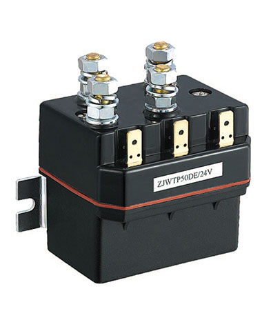
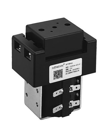
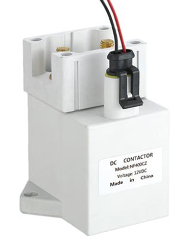
A DC contactor is an electromagnetic switch designed to control the flow of DC power in a circuit. It operates by using an electromagnet to open or close electrical contacts, allowing or interrupting the current supply to a load. Unlike alternating current (AC) contactors, DC contactors are specifically engineered to handle the unique characteristics of DC, such as the absence of zero-crossing points (which can cause arcing) and the need for effective arc suppression.
Key Components:
-
Electromagnet Coil: When energized with DC voltage, it generates a magnetic field that pulls the movable contact towards the fixed contact.
-
Contacts: Include main contacts (for carrying high current to the load) and auxiliary contacts (for control or signaling purposes).
-
Arc Suppression System: Typically uses arc chutes or magnetic blowouts to extinguish arcs formed when contacts open, preventing damage to the contactor.
-
Spring Mechanism: Returns the contacts to their original position when the coil is de-energized.
Wiring the Control Circuit
The control circuit is responsible for energizing or de-energizing the contactor’s coil, which in turn controls the main power circuit. It operates at a lower voltage than the power circuit (e.g., 12V, 24V DC) for safety and ease of control.
Step-by-Step Wiring Guide:
-
Disconnect Power: Always start by turning off the power supply to the control circuit to avoid electric shock.
-
Identify Coil Terminals: Locate the coil terminals on the contactor (usually labeled “A1” and “A2”). Check the contactor’s datasheet to confirm the required coil voltage (e.g., 24V DC).
-
Connect Control Voltage Source: Run a wire from the positive terminal of the control voltage source (e.g., a battery or power supply) to one coil terminal (A1). Connect another wire from the negative terminal of the source to a control device (e.g., a switch, relay, or microcontroller).
-
Add Control Devices: Connect the other end of the control device to the second coil terminal (A2). Common control devices include pushbuttons, limit switches, or PLC outputs—these devices determine when the contactor coil is energized.
-
Install Protection Components: Add a flyback diode (also called a freewheeling diode) in parallel with the coil, reverse-biased (cathode to A1, anode to A2). This suppresses voltage spikes when the coil is de-energized, protecting control circuit components.
-
Test the Control Circuit: Reconnect the control power and activate the control device. The contactor should click, indicating the coil is energized. If not, check for loose connections or incorrect voltage.
Wiring the Power Circuit
The power circuit carries the high DC current to the load (e.g., a motor, battery bank). Proper wiring here is critical to prevent overheating, arcing, and equipment failure.
Step-by-Step Wiring Guide:
-
Isolate Power Source: Disconnect the main DC power supply (e.g., battery pack, rectifier) before starting.
-
Identify Main Contacts: Locate the main power terminals on the contactor, typically labeled “L1” (line input) and “T1” (load output) for single-pole contactors, or “L1/L2/L3” and “T1/T2/T3” for multi-pole models.
-
Connect Power Input: Run heavy-gauge wires (sized according to the contactor’s current rating) from the positive terminal of the main power source to the “L” terminal(s) of the contactor. Use appropriate wire lugs and tighten terminals securely to avoid resistance and overheating.
-
Connect Load: Connect wires from the contactor’s “T” terminal(s) to the input terminals of the load (e.g., motor, inverter). Ensure the load’s current rating does not exceed the contactor’s rated current.
-
Grounding: Ground the contactor’s frame (if equipped) and the load to prevent electrical hazards.
-
Install Overcurrent Protection: Add a DC circuit breaker or fuse in series with the power input to protect against short circuits or overloads. The rating should match the contactor and load requirements.
-
Inspect and Test: Double-check all connections for tightness and proper insulation. Reconnect the main power and activate the control circuit—verify that the load receives power when the contactor is energized and loses power when de-energized.
Applications of DC Contactors
DC contactors are widely used in systems where DC power needs to be switched on or off. Common applications include:
-
Electric Vehicles (EVs) and Hybrid Electric Vehicles (HEVs): Control power flow between the battery pack, motor controller, and charging system. They also manage auxiliary systems like heating and cooling.
-
Industrial Automation: Switch DC motors, solenoids, and other DC loads in manufacturing machinery, conveyor systems, and robotics.
-
Renewable Energy Systems: Manage power from solar panels or wind turbines to batteries, inverters, or the grid. They help protect batteries from overcharging and disconnect loads during maintenance.
-
Marine and Aerospace: Handle DC power in ships, boats, and aircraft for lighting, navigation equipment, and propulsion systems (in electric boats).
-
Battery Energy Storage Systems (BESS): Connect and disconnect battery banks to the grid or load, ensuring safe charging and discharging.
Summary:
DC contactors are vital for safe and reliable control of DC power in various applications, from EVs to renewable energy systems. Understanding their structure—including the electromagnet coil, contacts, arc suppression system, and spring mechanism—is foundational to proper wiring. When connecting a DC contactor, the control circuit (low-voltage, with a flyback diode for protection) and power circuit (high-current, with overcurrent protection and secure wiring) must be handled with precision. By selecting the right contactor for the application and following best practices for wiring and safety, you can ensure the longevity and efficiency of your electrical system. Whether in industrial settings or everyday tech, DC contactors remain a cornerstone of DC power management.
FAQ
Q1: What’s the difference between a DC contactor and an AC contactor?
A: AC contactors rely on AC’s zero-crossing to suppress arcing, while DC contactors use arc chutes or magnetic blowouts. DC contactors also have a simpler coil design (no shading rings) since DC magnetic fields are constant. Using an AC contactor for DC applications can lead to overheating and contact damage.
Q2: How do I select the right DC contactor for my application?
A: Consider three key factors: (1) Rated Current: Match or exceed the load’s maximum current. (2) Rated Voltage: Ensure the contactor can handle the system’s DC voltage. (3) Coil Voltage: Choose a coil voltage compatible with your control circuit (e.g., 12V, 24V, 48V DC).
Q3: Why is a flyback diode needed in the control circuit?
A: When the contactor coil is de-energized, the collapsing magnetic field generates a high-voltage spike. The flyback diode provides a path for this current, protecting the control circuit’s switches, relays, or microcontrollers from damage.
Q4: What causes arcing in DC contactors, and how is it prevented?
A: Arcing occurs because DC current doesn’t have zero-crossing points, so the current continues to flow when contacts open. DC contactors use arc chutes (which cool and stretch the arc) or magnetic blowouts (which redirect the arc into the chute) to extinguish it quickly.