Contactors are critical electromagnetic switching devices used to control high-power electrical loads, and understanding the differences between AC (Alternating Current) and DC (Direct Current) contactors is essential for safe and efficient electrical system operation. Below is a detailed breakdown of key concepts, differences, and practical guidelines.
1. What Are Contactors?
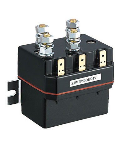
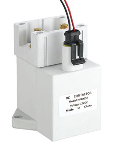
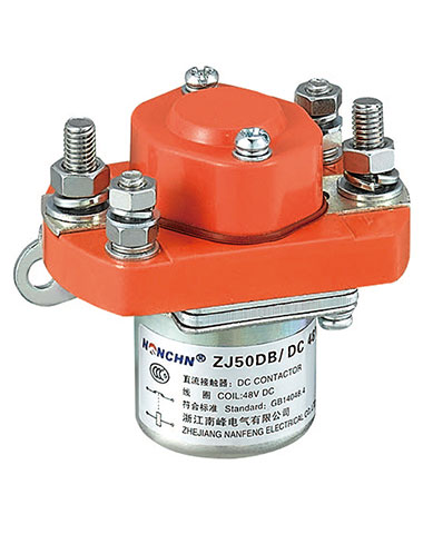
A contactor is an electromagnetic switch designed to remotely control the on/off state of high-current electrical circuits. Unlike ordinary switches (which handle low currents), contactors can manage loads ranging from a few amps to hundreds of amps, making them indispensable in industrial, commercial, and even residential electrical systems.
Key components of a contactor include:
Electromagnetic Coil: Receives a control signal (low current) to generate a magnetic field.
Movable Armature: Attracted by the coil’s magnetic field to drive contact movement.
Main Contacts: Carry the main load current (high current) to connect or disconnect the circuit.
Auxiliary Contacts: Handle low-current control signals (e.g., for interlocking or status feedback).
Arc Suppression Device: Prevents electrical arcs (sparks) from damaging contacts when the circuit is broken.
2. How Does a Contactor Device Work?
The operation of a contactor relies on the principle of electromagnetic induction, and its workflow can be divided into four simple steps:
Coil Energization: When a low-current control signal (e.g., from a relay or controller) is applied to the coil, the coil generates a magnetic field.
Armature Attraction: The magnetic field pulls the movable armature toward the coil, which in turn pushes the main contacts closed.
Circuit Connection: Once the main contacts close, the high-power load (e.g., a motor or heater) is connected to the power supply, and the load starts operating.
Coil De-Energization: When the control signal is removed, the magnetic field disappears. A spring pulls the armature and main contacts back to their original position, disconnecting the load from the power supply.
3. Difference Between AC Contactors and DC Contactors
AC and DC contactors differ significantly in design and performance, primarily due to the inherent characteristics of AC and DC currents (AC is alternating and periodic; DC is constant and unidirectional). The key differences are summarized below:
| Aspect | AC Contactor | DC Contactor |
|---|---|---|
| Coil Design | Uses laminated iron cores to reduce eddy current losses (caused by AC’s alternating magnetic field). | Uses solid iron cores (no eddy currents in DC’s constant magnetic field); coil resistance is higher to limit current. |
| Main Contacts | Contacts are often smaller, with arc-suppression notches or multiple parallel contacts (to handle AC’s zero-crossing arcs). | Contacts are larger and thicker (to withstand DC’s continuous arcs); often made of arc-resistant materials (e.g., silver-tungsten). |
| Arc Suppression | Relies on arc chutes (metal grids that split arcs into small segments) or zero-crossing (AC current naturally drops to zero 100–120 times per second, extinguishing arcs). | Uses magnetic blowouts (a magnetic field forces arcs into an arc chute) or vacuum chambers (since DC arcs do not have zero-crossing points and are harder to extinguish). |
| Current Handling | Designed for sinusoidal AC current; rated for “rms current” (root mean square value). | Designed for constant DC current; rated for “average current” (no waveform fluctuations). |
| Power Consumption | Coil power consumption is lower (due to laminated cores reducing energy loss). | Coil power consumption is higher (solid cores and higher resistance require more energy to maintain the magnetic field). |
4. Why Cannot AC and DC Contactors Be Substituted for One Another?
Substituting AC and DC contactors leads to immediate equipment damage or safety hazards, as their designs are not compatible with the opposite current type. The main risks are:
AC Contactor Used in DC Circuits:
Coil Overheating: AC coils have low resistance (optimized for AC’s impedance). In a DC circuit, the coil will draw excessive current, causing overheating and burnout.
Contact Damage: AC contactors lack effective DC arc suppression. DC’s continuous arcs will melt or weld the contacts shut, leading to circuit failure or fires.
Unreliable Operation: The AC coil’s laminated core cannot generate a stable magnetic field in DC, causing the armature to vibrate and contacts to bounce (resulting in poor load control).
DC Contactor Used in AC Circuits:
Weak Magnetic Force: DC coils have high resistance (to limit DC current). In an AC circuit, the coil’s impedance (combined resistance and reactance) is too high, generating a weak magnetic field that cannot reliably pull the armature.
Contact Wear: DC contacts are designed for constant arcs, not AC’s zero-crossing arcs. The frequent, small arcs in AC will wear contacts quickly, shortening the contactor’s lifespan.
Eddy Current Loss: DC contactors use solid cores, which generate large eddy currents in AC circuits. This causes core overheating and coil damage over time.
5. Choosing the Right Contactor for Your Needs
To select a contactor that matches your system, follow these four steps:
Confirm Current Type: First, determine whether your load uses AC or DC power—this directly dictates whether you need an AC or DC contactor (no substitutions).
Calculate Load Parameters:
For AC: Check the load’s rms voltage (e.g., 220V, 380V) and rms current (ensure the contactor’s rated current is 1.2–1.5 times the load current to account for surges).
For DC: Check the load’s rated voltage (e.g., 12V, 24V, 220V DC) and average current (similarly, select a contactor with a rated current 1.2–1.5 times the load current).
Consider Environmental Factors: Choose a contactor with an appropriate enclosure rating (e.g., IP20 for indoor dry areas, IP65 for dusty/wet environments) to prevent damage from moisture, dust, or temperature extremes.
Check Auxiliary Functions: If your system needs interlocking (e.g., preventing two contactors from operating simultaneously) or status feedback, select a contactor with the required number of auxiliary contacts (normally open or normally closed).
6. Contactor Applications
AC and DC contactors are used in distinct scenarios based on their compatibility with current types:
AC Contactor Applications
- Industrial machinery: Controlling AC motors (e.g., conveyor belts, pumps, fans).
- Commercial equipment: Air conditioners, refrigerators, and electric heaters.
- Residential systems: Main switches for high-power appliances (e.g., electric stoves) or home backup generators.
- Power distribution: Switching power in low-voltage electrical panels (e.g., in factories or office buildings).
DC Contactor Applications
- Automotive industry: Controlling electric vehicle (EV) powertrains, battery charging systems, or windshield wipers.
- Renewable energy: Connecting solar inverters (DC side) or wind turbine DC circuits to batteries.
- Transportation: Controlling DC motors in elevators, trams, or forklifts.
- Emergency systems: DC backup power supplies (e.g., UPS) for hospitals or data centers.
Conclusion
AC and DC contactors differ significantly in structure, operating principle, arc control, coil design, and interrupting capacity. Therefore, they each have their own advantages and disadvantages for different power supply types and load scenarios. Simply substituting one type for the other is not acceptable; doing so could result in performance degradation, shortened lifespan, and even safety risks. Choosing the right contactor requires comprehensive consideration of load characteristics, operating power supply, coil voltage, switching frequency, rated capacity, and environmental conditions. A well-selected contactor, combined with a reliable manufacturer and a reasonable safety margin, is key to ensuring stable and durable system operation.