DC contactors are vital electromechanical switches controlling high-power direct current (DC) circuits in applications like electric vehicles, solar power systems, battery management, industrial machinery, and railways. Ensuring their reliable operation is critical for safety and system performance. This guide outlines the essential steps for testing a DC contactor.
1. What is a Contactor?
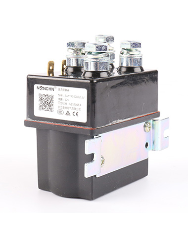
A contactor is a heavy-duty, electrically controlled switch designed to handle high current loads (from tens to thousands of amperes). Unlike a simple relay for lower currents, contactors use an electromagnetic coil to mechanically open or close sets of power contacts. Their primary function is to remotely or automatically connect and disconnect power to motors, heaters, lighting banks, capacitors, or other high-current devices. DC contactors are specifically engineered to interrupt DC current, which presents unique challenges (like sustained arcs) compared to AC.
2. Key Components of a DC Contactor:
-
Coil (Electromagnet): The input side. When energized with the correct DC voltage, it creates a magnetic field.
-
Armature (Moving Core): A movable iron piece attracted by the energized coil's magnetic field.
-
Contacts:
-
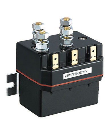
Main Power Contacts: Heavy-duty contacts (usually silver alloy) that carry the main load current. They close to connect the circuit and open to disconnect it.
-
Auxiliary Contacts: Smaller contacts integrated into the contactor used for control signaling (e.g., indicating contactor status to a PLC).
-
-
Spring(s): Returns the armature and opens the main contacts when the coil is de-energized.
-
Frame/Enclosure: Provides structural support, insulation, and protection.
-
Arc Suppression System (Crucial for DC): A dedicated chamber (arc chute) with splitter plates designed to rapidly stretch, cool, and extinguish the powerful arc generated when interrupting DC current. This is a defining feature of DC contactors.
-
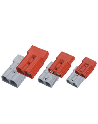
Terminals: Connection points for the coil and the main power circuits.
3. Types of Contactors (Relevance to DC):
-
AC Contactors: Designed for alternating current. Use shading coils to prevent hum, rely partially on AC current zero-crossings for arc extinction. Generally NOT suitable for DC loads.
-
DC Contactors: Specifically designed for direct current. Feature robust arc chutes to forcibly extinguish the DC arc. Have coils rated for DC voltage. Required for DC applications.
-
Polarized vs. Non-Polarized: Some DC contactors are polarized (coil +/- matters), while others are non-polarized. Check the datasheet.
-
Application Specific: Available in various sizes, current ratings, coil voltages, and with different numbers/arrangements of main and auxiliary contacts.
Preparing for DC Contactor Testing
Safety Precautions
- Power Off: Before starting any testing, ensure that the power supply to the circuit containing the DC contactor is completely turned off. This is to prevent any electric shock or damage to the testing equipment or the contactor itself.
- Discharge Capacitors: If the circuit includes capacitors, make sure to discharge them properly. Capacitors can store electrical energy even after the power is turned off, and discharging them will eliminate the risk of electric shock during testing.
- Personal Protective Equipment (PPE): Wear appropriate PPE, such as insulated gloves, safety glasses, and anti-static clothing, to protect yourself from potential hazards during the testing process.
Tools and Equipment
- Multimeter: A digital multimeter is essential for measuring electrical quantities such as voltage, current, and resistance. It can be used to test the coil resistance, contact resistance, and voltage across the contacts.
- Ohmmeter: An ohmmeter can be used to measure the resistance of the coil and the contacts. It provides a more accurate measurement of low resistances compared to a multimeter in some cases.
- Power Supply: A regulated DC power supply is needed to apply the rated voltage to the contactor coil during testing. It should be capable of providing the correct voltage and current required by the contactor.
- Test Leads and Probes: High-quality test leads and probes are necessary to make reliable electrical connections during testing. They should be insulated and have appropriate connectors for the testing equipment and the contactor terminals.
- Visual Inspection Tools: A flashlight and a magnifying glass can be used for visual inspection of the contactor's external and internal components. This helps in detecting any obvious signs of damage, such as burnt contacts, loose connections, or cracked housing.
Visual Inspection
- Exterior Check: Inspect the housing of the contactor for any signs of physical damage, such as cracks, dents, or melted areas. Check the terminals for loose connections, corrosion, or burnt marks. Ensure that the label on the contactor is clear and legible, providing information about the rated voltage, current, and other specifications.
- Internal Inspection: If possible, open the housing of the contactor (following the manufacturer's instructions) and inspect the internal components. Look for burnt or pitted contacts, worn-out springs, or a damaged armature. Check the condition of the coil for any signs of overheating, such as discolored insulation or a burnt smell.
DC Contactor Testing Procedures
1. Coil Testing
Resistance Check
- Use ohmmeter: Measure resistance across coil terminals.
- Normal: Matches manufacturer’s rated value (±10% tolerance).
- Fault: High resistance (open coil); low resistance (short circuit).
Voltage Application Test
- Apply rated DC voltage to the coil:
- Armature should click into place; contacts close.
- Buzzing noise? Check armature alignment or coil voltage (must be within rated range).
2. Contact Testing
Contact Resistance (Energized State)
- Multimeter (low-resistance mode) across main contacts:
- Ideal: <100 mΩ (near-zero).
- High resistance (≥1Ω): Dirty/pitted contacts (clean or replace).
Operation Test
- Cycle power 5x:
- Smooth opening/closing; auxiliary contacts toggle correctly.
- Sticking? Inspect for debris or misaligned armature.
3. Dielectric Strength Test
- Megohmmeter (500V/1000V DC):
- Test insulation between coil & housing, main/auxiliary contacts.
- Result: ≥10 MΩ (good insulation); <1 MΩ = faulty insulation (replace contactor).
4. Operating Voltage Range Test
- Vary coil voltage from 85% to 110% of rated value:
- Pickup Voltage: Contacts close (should be ≤85% rated voltage).
- Dropout Voltage: Contacts open (should be ≥10% rated voltage).
Common Faults & Troubleshooting
|
Issue |
Symptoms |
Causes |
Solutions |
|
Coil Failure |
No activation; buzzing noise. |
Broken wire, short circuit, overheating. |
Measure resistance; replace coil if abnormal. |
|
Contact Wear |
High resistance, arcing, overheating. |
Frequent high-current switching; dirty contacts. |
Clean with abrasive paper (minor); replace (severe). |
|
Sticking Contacts |
Delayed/open/close; erratic operation. |
Debris, misaligned armature, weak spring. |
Clean interior; check armature/spring; replace if damaged. |
|
Low Contact Pressure |
Arcing, voltage drop. |
Worn springs, misadjustment. |
Test spring tension; replace springs or contactor. |
Conclusion:
Regular testing and maintenance of DC contactors are essential for system safety and reliability. By following a systematic approach – emphasizing safety preparation, visual inspection, and the key electrical tests (coil, insulation, contact resistance, continuity) – you can effectively diagnose contactor health. Understanding common failure modes helps target troubleshooting efforts. When in doubt, or if tests indicate significant deterioration, replacing the contactor is the safest course of action. Always prioritize safety and consult manufacturer documentation.