A DC contactor is a vital electromechanical device designed to control the flow of direct current (DC) in electrical circuits, acting as a switch to safely connect or disconnect power. Below is a detailed breakdown of its function, structure, applications, and selection criteria, along with frequently asked questions.
What’s a DC Contactor?
A DC contactor is an electrical switch specifically engineered for DC circuits. Unlike AC contactors, it handles the unique challenges of DC power, such as arc formation during disconnection. It enables efficient control of high-voltage and high-current DC systems, ensuring safe operation in various industries.
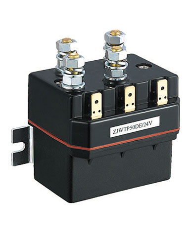
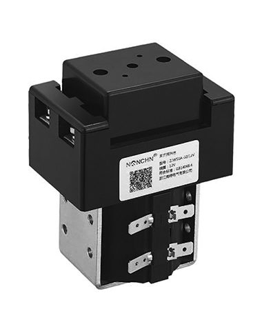
A DC contactor comprises three core components
1. Contact System
Main Contacts: Carry the primary current, consisting of fixed and movable contacts that close to connect the circuit or open to disconnect it.
Auxiliary Contacts: Provide feedback or control secondary circuits, often used for signaling or interlocking.
2. Electromagnetic System
Coil: When energized, generates a magnetic field that pulls the movable iron core (armature) toward the fixed pole.
Armature and Yoke: Translate magnetic force into mechanical motion to actuate the contacts.
Enclosure: Insulates and protects internal components from environmental hazards.
3. Arc Extinguishing System
Blowout Coils and Magnetic Fields: Elongate and redirect electric arcs formed during high-current disconnection, quenching them quickly to prevent damage.
Working Principle of DC Contactors
The operation of a DC contactor relies on two key processes:
1. Contactor Excitation Process (Turning On)
Magnetic Field Creation: Applying voltage to the coil generates a magnetic field.
Armature Movement: The magnetic field attracts the armature toward the coil.
Contact Closing: The armature pushes the contacts together, forming a low-resistance path for DC current.
2. Contactor De-Excitation Process (Turning Off)
Magnetic Field Collapse: Removing voltage from the coil dissipates the magnetic field.
Armature Return: A spring or passive mechanism pulls the armature back to its original position.
Contact Opening: The contacts separate, interrupting current flow.
3. Advantages of the Excitation/De-Excitation Process
Excitation: Enables high-efficiency power transmission with low resistance.
De-Excitation: Ensures safety by quickly disconnecting power during faults or maintenance.
Applications of DC Contactors
DC contactors are critical in various industries:
Electric Vehicles (EVs): Control power flow between the battery and motor, optimizing energy use.
EV Charging Stations: Manage high-current charging connections safely.
Renewable Energy Systems: Connect and isolate solar panels, wind turbines, and energy storage devices.
Energy Storage Systems (ESS): Switch batteries and supercapacitors in and out of the grid.
Industrial Automation: Control DC motors, robotics, and process equipment.
HVDC Transmission: Handle high-voltage DC power distribution over long distances.
Choosing a Suitable DC Contactor
Selecting the right contactor is critical for safety and performance:
1. Voltage Rating (Nominal & Max): Must exceed the system's operating voltage and account for voltage spikes.
2. Continuous Current Rating: Must handle the maximum continuous current the load draws without overheating.
3. Breaking Capacity/Interrupting Rating: The maximum current the contactor can safely interrupt at its rated voltage. This is crucial for DC due to arcing.
4. Coil Voltage: Matches the available control circuit voltage (e.g., 12V, 24V, 48V).
5. Pole Configuration: Number of isolated contact sets (e.g., 1-pole, 2-pole).
6. Arc Extinction Method: Suitable for the application's voltage/current levels.
7. Environmental Factors: IP rating (dust/water resistance), temperature range, shock/vibration resistance.
8. Standards & Certifications: Look for relevant safety standards (e.g., UL, IEC, automotive standards).
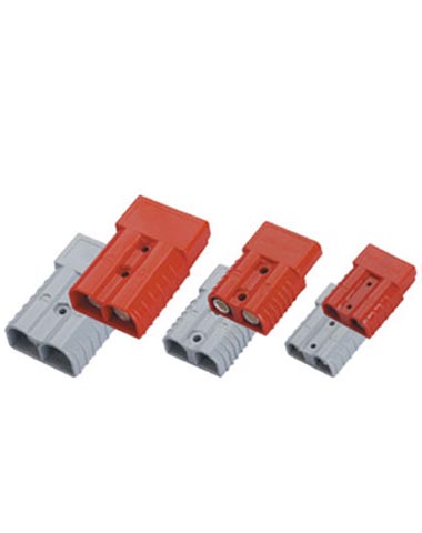
9. Mounting & Connection Type: Screw terminals, blade terminals, PCB mount, etc.
Conclusion
DC contactors are the backbone of high-voltage DC systems, enabling precise control through their electromagnetic and mechanical design. By understanding their structure, working principles, and application needs, industries can leverage them to build safer, more efficient electrical infrastructures in EVs, renewables, and beyond. Proper selection and maintenance ensure their reliability in critical roles.
FAQ
Q1: How does a DC contactor differ from an AC contactor?
A: DC contactors are designed to handle steady current flow, requiring robust arc extinguishing systems due to the lack of natural zero-crossing points in DC. AC contactors, conversely, rely on current zero-crossings to quench arcs more easily.
Q2: Why is an arc extinguishing system important in DC contactors?
A: DC arcs are persistent and can damage contacts if not extinguished quickly. The system uses magnetic fields to stretch and cool arcs, ensuring safe operation.
Q3: Can a DC contactor be used in an AC circuit?
A: No. DC contactors lack the design features (e.g., eddy current damping) needed for AC applications, which can lead to overheating or failure.
Q4: How do I test the reliability of a DC contactor?
A: Test under actual operating conditions, checking coil voltage tolerance, contact bounce, and arc extinguishing efficiency. Ensure it meets industry standards for your application (e.g., EVs, renewables).