What is a DC contactor?
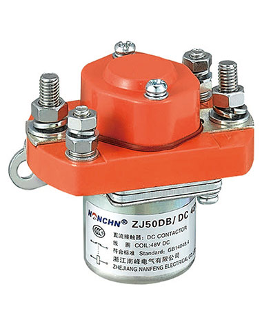
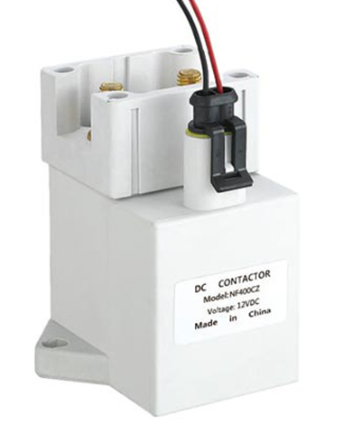
A DC contactor is an electrical switching device designed to control the flow of direct current (DC) in a circuit. It acts as a remote-controlled switch, enabling safe and efficient opening or closing of high-power DC circuits.
Key features:
- Unlike AC contactors, it handles DC’s unique trait of no zero-crossing in current waveforms (which can cause sustained arcing).
- Core components: coil (electromagnet), stationary/movable contacts, arc suppression system, and protective housing.
- Common applications: electric vehicles, battery systems, industrial machinery, and solar power setups.
Working principle of DC contactor
Based on electromagnetic attraction and mechanical switching:
1. Coil Activation: Applying low-voltage DC to the coil generates a magnetic field, magnetizing the core and creating electromagnetic force.
2. Contact Closure: The force pulls the spring-loaded movable contact toward the stationary contact, closing the main DC circuit and allowing current to flow to the load.
3. Coil Deactivation: Interrupting coil current collapses the magnetic field. The spring returns the armature, separating contacts and opening the circuit.
4. Arc Suppression: Critical for DC—uses arc chutes, magnetic blowout coils, or resistors to quickly extinguish arcs (since DC has no natural current zero).
Contactor vs. Relay
| Feature | Contactor | Relay |
| Power Handling | High (hundreds to thousands of amps) | Low (up to 10 amps) |
| Contact Design | Large, robust (silver/copper alloys) | Small, suited for low power |
| Arc Suppression | Dedicated systems (essential for DC) | Rarely needed (low current) |
| Purpose | Directly controls power to loads | Switches control circuits or signals |
Types of DC contactor
DC contactors are classified based on their design, application, or contact configuration:
1. Polarized vs. Non-Polarized: Polarized DC contactors use a permanent magnet to enhance the magnetic field, improving contact force and arc suppression. Non-polarized contactors rely solely on the coil’s electromagnetic field.
2. Single-Pole vs. Multi-Pole: Single-pole contactors control a single circuit (one set of contacts), while multi-pole contactors (e.g., 2-pole or 4-pole) switch multiple circuits simultaneously, useful for three-phase DC systems or redundant setups.
3. Latching vs. Non-Latching: Latching contactors remain in their last position (open or closed) even after the coil is de-energized, using a mechanical latch. They save energy in applications where the switch state rarely changes. Non-latching contactors return to their default position when the coil is de-energized.
4. Application-Specific: Examples include automotive DC contactors (for electric vehicle batteries), traction contactors (for trains or trams), and industrial contactors (for machinery).
How to wire a DC contactor
Wiring a DC contactor involves connecting the control circuit (coil) and the main power circuit (load). Follow these general steps (always consult the manufacturer’s datasheet for specifics):
1. Identify Terminals: DC contactors have two sets of terminals:
Coil Terminals: Usually marked “A1” and “A2,” these connect to the low-voltage control power source (e.g., 12V or 24V DC).
Main Contacts: Marked “L1/L2” (line side, input) and “T1/T2” (load side, output), these carry the high-power DC current to the load (e.g., a motor).
2. Wire the Coil: Connect the control voltage source (e.g., a switch or microcontroller) to A1 and A2. Ensure the voltage matches the coil’s rating (overvoltage can damage the coil).
3. Wire the Main Circuit: Connect the positive DC supply to the line terminal (L1), and the load (e.g., motor) to the corresponding load terminal (T1). Connect the other end of the load to the negative supply. For multi-pole contactors, repeat for additional poles.
4. Add Protection: Include fuses or circuit breakers in the main circuit to prevent overloads. For arc-sensitive applications, ensure the contactor’s arc suppression system is properly installed.
5. Test: Energize the coil to verify that the contacts close and the load operates. De-energize to confirm the contacts open and the load stops.
By understanding these aspects, one can effectively utilize DC contactors in various high-power DC systems, ensuring safe and reliable operation.
FAQ
Q: Can an AC contactor be used with DC?
A: No. AC contactors lack the arc suppression needed for DC circuits, leading to excessive arcing and contact damage.
Q: Why do DC contactors need arc suppression?
A: DC current has no zero-crossing, so arcing persists longer when contacts open. Arc suppression prevents contact erosion and fire risks.
Q: What causes a DC contactor to fail?
A: Common causes include worn contacts (from arcing), coil burnout (due to overvoltage), or mechanical jamming (from dirt or debris).
Q: How to select a DC contactor?
A: Consider the rated current (must exceed the load current), coil voltage, number of poles, and application (e.g., automotive vs. industrial).
Q: Can a DC contactor switch AC?
A: While possible in some cases, it is not recommended. AC’s alternating current may cause inefficient arcing and reduce contactor lifespan.