
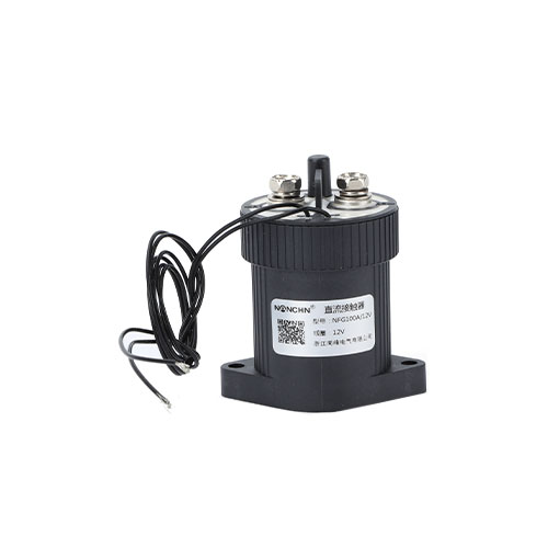
100A contact switching capacity. Permanent magnets generate a transverse magnetic field to achieve high-voltage DC cutoff.


Features
• Fully sealed structure, with a protection level of IP67.
• Small size and light weight.
• Fully complies with ROHS requirements.
• Suitable for electric vehicle pre-charging systems, battery switches and backup power supplies, DC power control, circuit safety protection, etc.
Performance parameters
|
Parameter |
Unit |
Value |
|
|
Main contact form |
/ |
one normal open |
|
|
Operating voltage of contact |
V (DC) |
12~1000 |
|
|
Rated control capacity |
/ |
100A 450V(DC-1) |
|
|
Rated short-time withstand current and duration |
/ |
150A 300s |
|
|
200A 30s |
|||
|
contact voltage drop |
mV |
≤80@100A |
|
|
Action time (including contact bounce) |
ms |
≤25 |
|
|
release time |
ms |
≤12 |
|
|
Contact bounce time |
ms |
≤6 |
|
|
Maximum breaking current (only allowed to break once) |
/ |
1000A,80V |
|
|
Load life (non-polarized, pure resistive load) |
time |
100A, 450V |
5000 |
|
100A, 750V |
1000 |
||
|
80A, 1000V |
100 |
||
|
mechanical life |
time |
1,000,00 |
|
|
insulation resistance |
MΩ |
100 (under the condition of 500V (DC)) |
|
|
Withstand Voltage |
V (AC) |
2200V (AC) 50 Hz/60 Hz (Leakage current ≤1mA) |
|
|
Operating Temperature |
℃ |
-40~+85 |
|
|
Operating Humidity |
/ |
5%~90% |
|
|
Impact, 11ms, 1/2 sine wave, peak value |
G |
20 |
|
|
Vibration, sine wave, 80~2000Hz, peak value |
G |
20 |
|
|
Rated duty |
/ |
Continuous working duty |
|
|
Weight (approximately) |
g |
170 |
|
|
Installation method |
/ |
arbitrary |
|
Coil parameters
|
Coil type |
Non-energy-saving type |
||
|
Rated voltage of coil (Us) |
12V (DC) |
24V (DC) |
48V (DC) |
|
Operating voltage range (@20℃) |
85%Us~110%Us |
||
|
Pick up voltage (V (DC)) @20℃ |
≤9 |
≤18 |
|
|
Release voltage (V (DC)) @20℃ |
≥1 |
≥2 |
≥4 |
|
Maximum surge current of coil (A) |
/ |
/ |
/ |
|
Maximum surge time (ms) |
/ |
/ |
/ |
|
Coil holding current (A) @20℃ |
≤0.6 |
≤0.3 |
≤0.15 |
|
Coil holding power (W) @20℃ |
≤6 |
≤6 |
≤6 |
Note:
1. The rated electrical endurance of the product is based on resistive load testing, with the maximum inductance of its load not exceeding 27μH; for inductive loads, please consult the factory.
2. The above figure is drawn based on the estimation of test and inferred data. It is recommended that users conduct tests and confirmations based on the actual usage route.
3. When the dielectric withstand voltage and insulation resistance of the product are less than the parameters listed in the product parameter table, the product is defined as having reached the end of its lifespan.
Model Description
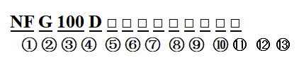
①: Product model
②: Contact voltage: (N: Low voltage; G: High voltage)
③: Rated operating current: "100" = 100A
④: A: Equipped with energy-saving circuit board
⑤: B: One normal close; (None: One normal open)
⑥: C: Magnetic latching
⑦: D: Single coil
⑧: T: Ceramic base
⑨: S: one normal open auxiliary contacts
⑩: Rated voltage of coil: "6" = 6V (DC), "12" = 12V (DC), "24" = 24V (DC), "48" = 48V (DC), "72" = 72V (DC)
⑪: Connection method: (N: External thread; K: Internal thread)
⑫: Installation method: (None: bottom installation)
⑬: Customer special code: 01-99
Example: NFG100DK/24V indicates that the rated current of the product load is 100A (resistive), the main contact form is one normal open (internal thread), the coil voltage is DC 24V, and the bottom installation method is used.
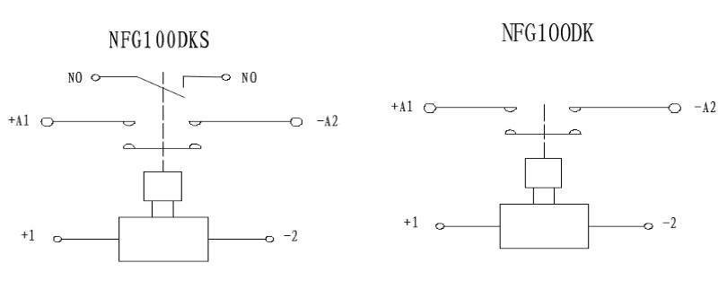
Circuit principle
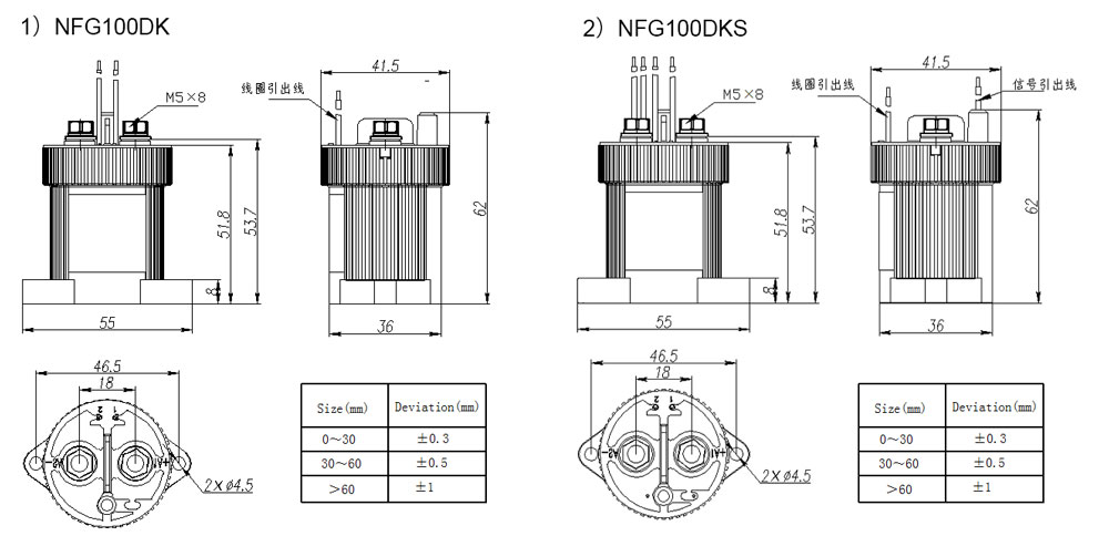
Outline dimension diagram
Precautions for use
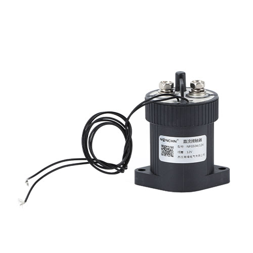
50A contact switching capacity. Permanent magnets generate a transvers
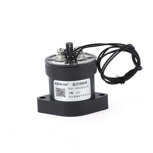
30A contact switching capacity. Permanent magnets generate a transvers
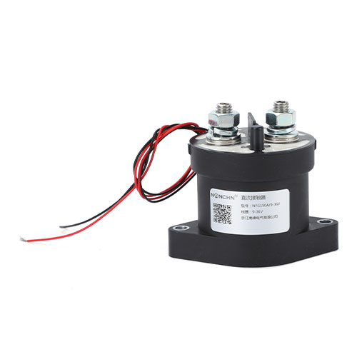
150A contact switching capacity. Permanent magnets generate a transver
150A contact switching capacity. Permanent magnets generate a transver