
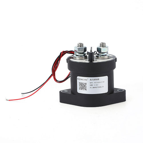
300A contact switching capability. The permanent magnet blows a magnetic field horizontally to achieve high-voltage direct current cut-off.


Features
• Fully sealed structure, protection level IP67.
• Energy saving coils to reduce coil holding power.
Fully comply with ROHS requirements.
• Suitable for battery switch and backup power supply, DC power control, circuit safety protection, etc.
Performance parameters
|
Parameter |
Unit |
Value |
||
|
Main contact form |
/ |
one normal open |
||
|
Contact working voltage |
V (DC) |
12~450 |
||
|
Rated control capacity |
/ |
300A 450V(DC-1) |
||
|
Rated short-time withstand current and duration |
/ |
400A 1200s |
||
|
contact voltage drop |
mV |
≤ 80 @ 100A current |
||
|
Action time (including contact bounce) |
ms |
≤30 |
||
|
release time |
ms |
≤12 |
||
|
Contact bounce time |
ms |
≤6 |
||
|
Maximum breaking current (only once on/off) |
/ |
3000A;100V |
||
|
Transform the electrical life of the load (non-polar, purely resistive load) |
time |
300A、450V |
1000 times |
|
|
300A、300V |
3000 times |
|||
|
300A、220V |
6000 times |
|||
|
mechanical life |
time |
1,00,000 |
||
|
Auxiliary contact (Optional) |
contact form |
/ |
One normal open |
|
|
Contact load rating |
/ |
2A/30V (DC)、3A/125V (AC) |
||
|
Minimum value of contact load |
/ |
100mA/8V |
||
|
insulation resistance |
MΩ |
100 (under 500V (DC) conditions) |
||
|
Withstand Voltage |
V (AC) |
3500V (AC) 50 Hz/60 Hz (leakage current ≤ 1mA) 1000V (AC) 50Hz/60Hz (between auxiliary contacts) |
||
|
Operating Temperature |
℃ |
-40~+85 |
||
|
Operating Humidity |
/ |
5%~90%RH |
||
|
altitude |
m |
4000 |
||
|
Shock, 11ms, 1/2 sine wave, peak value |
G |
20 |
||
|
Vibration, sine wave, 80-2000Hz, peak value |
G |
20 |
||
|
Rated working duty |
/ |
Continuous working duty |
||
|
Weight (approximately) |
g |
425 |
||
|
Installation method |
/ |
arbitrary |
||
Coil parameters
|
Coil type |
Non energy-saving type |
||
|
Rated voltage of coil (Us) |
12V (DC) |
24V (DC) |
48V (DC) |
|
Working voltage range (@ 20 ℃) |
85%Us~110%Us |
||
|
Pick up voltage (V (DC)) @ 20 ℃ |
≤9 |
≤18 |
≤36 |
|
Release voltage (V (DC)) @ 20 ℃ |
≥1 |
≥2 |
≥4 |
|
Maximum surge current of coil (A) |
/ |
/ |
/ |
|
Maximum surge time (ms) |
/ |
/ |
/ |
|
Coil power (W) @ 20 ℃ |
≤12 |
≤12 |
≤12 |
Note:
1. The rated electrical life of the product is based on resistive load testing, and the maximum inductance of the load does not exceed 300 μ H;If there are inductive loads, please consult the factory.
2. The above figure is estimated based on testing and inference data, and it is recommended that users conduct testing and confirmation based on actual usage of the circuit.
3. When the dielectric withstand voltage and insulation resistance of the product are less than the parameters in the product parameter table, the product is defined as end-of-life.
Model Description
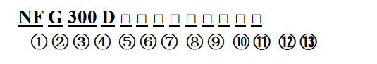
①:Product Model
②:Contact voltage: (none: low voltage; G: high voltage)
③:Rated working current: "300"=300A
④:A: Equipped with energy-saving circuit board
⑤:B: one normal close;(None: one normal open)
⑥:C: Magnetic latching
⑦:D: Single coil
⑧:T: Ceramic base
⑨:S: one normal open auxiliary contacts
⑩:Rated voltage of coil: "6"=6V (DC), "12"=12V (DC), "24"=24V (DC), "48"=48V (DC), "72"=72V (DC)
⑪:Connection method: (none: external thread; K=internal thread)
⑫:Installation method: (none: bottom installation)
⑬:Customer special code: 01-99
Example: NFG300DS indicates that the rated current of the product load is 300A (resistive), the main contact form is one normal open (external thread) with one normal open auxiliary contacts, the coil voltage is DC 12V, and the bottom installation method.
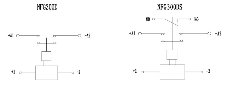
Circuit principle
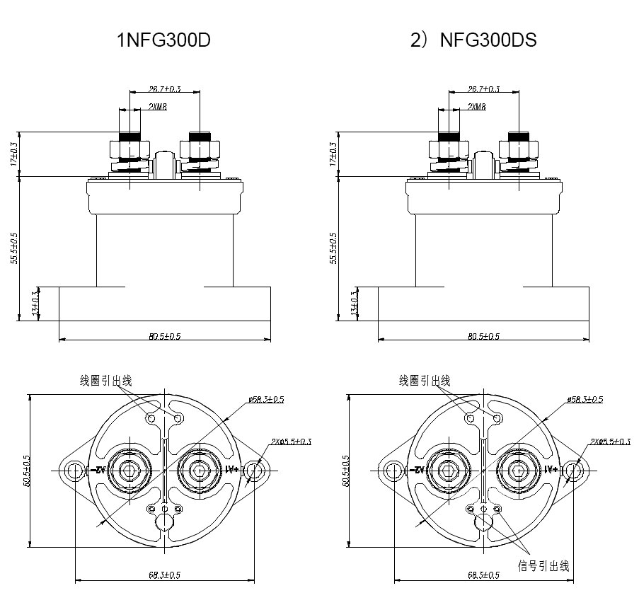
Outline dimension diagram
Precautions for use
300A contact switching capability. The permanent magnet blows a magnet
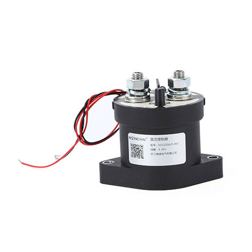
250A contact switching capacity. Permanent magnet transverse blow fiel
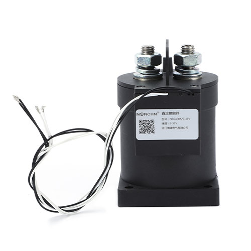
400A contact switching capability. The permanent magnet blows a magnet
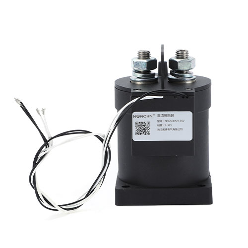
500A contact switching capability. The permanent magnet blows a magnet